Free with trial This image showcases a compact 16-LED microcontroller module, ideal for a variety of DIY projects and educational applications. The module's small form factor makes it perfect for integration into smaller devices or for use as a stand-alone learning tool. The visible LEDs are arranged in a way that allows for customizable patterns and displays. The microcontroller, a key component of the module. Microcontroller module illustrations Compact 16LED Microcontroller Module for DIY Projects and Educational Applications A Detailed Look at the. This image showcases a compact 16-LED microcontroller module, ideal for a variety of DIY projects and educational applications. The module's small form factor makes it perfect for integration into smaller devices or for use as a stand-alone learning tool. The visible LEDs are arranged in a way that allows for customizable patterns and displays. The microcontroller, a key component of the module
Free with trial This image shows a small microcontroller development board featuring a central integrated circuit, likely a microcontroller or a programmable logic chip, surrounded by various electronic components. The board includes two large cylindrical capacitors, resistors, and several through-hole pins for connections. The text 'Japan' and '10C' are visible on the board, indicating possible manufacturing. Microcontroller module illustrations Microcontroller development board with integrated capacitors and circuit components. This image shows a small microcontroller development board featuring a central integrated circuit, likely a microcontroller or a programmable logic chip, surrounded by various electronic components. The board includes two large cylindrical capacitors, resistors, and several through-hole pins for connections. The text 'Japan' and '10C' are visible on the board, indicating possible manufacturing
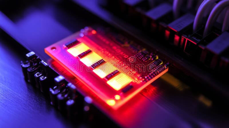
Free with trial A close-up view of a NOR flash memory module designed for embedded microcontroller applications. The illuminated circuit showcases advanced technology and design, reflecting modern electronic innovations. Microcontroller module illustrations NOR Flash Memory Module for Embedded Microcontroller Applications. A close-up view of a NOR flash memory module designed for embedded microcontroller applications. The illuminated circuit showcases advanced technology and design, reflecting modern electronic innovations
Free with trial This detailed close-up image showcases a NOR flash memory module embedded in a microcontroller circuit board, highlighting modern electronics technology. Microcontroller module illustrations Close-Up of NOR Flash Memory Module on Microcontroller Circuit Board. This detailed close-up image showcases a NOR flash memory module embedded in a microcontroller circuit board, highlighting modern electronics technology
Free with trial This detailed close-up image showcases a NOR flash memory module embedded in a microcontroller circuit board, highlighting modern electronics technology. Microcontroller module illustrations Close-Up of NOR Flash Memory Module on Microcontroller Circuit Board. This detailed close-up image showcases a NOR flash memory module embedded in a microcontroller circuit board, highlighting modern electronics technology
Free with trial This image depicts a small, green circuit board featuring a central microcontroller chip surrounded by various electronic components. The board includes multiple connectors, resistors, capacitors, and other passive components. The connectors appear to be for power input, data transfer, and peripheral device connections. Such boards are commonly used in embedded systems, robotics, and IoT devices. Microcontroller module illustrations Miniature electronic circuit board with central microcontroller chip and connectors. This image depicts a small, green circuit board featuring a central microcontroller chip surrounded by various electronic components. The board includes multiple connectors, resistors, capacitors, and other passive components. The connectors appear to be for power input, data transfer, and peripheral device connections. Such boards are commonly used in embedded systems, robotics, and IoT devices
Free with trial This image shows a small USB to serial converter module designed for converting USB data signals to serial communication protocols. The board features a USB type A port for connection to a host device, a microcontroller for data processing, and various passive components like capacitors and resistors. This type of module is commonly used in electronics projects for debugging, interfacing. Microcontroller module illustrations Compact usb to serial converter module with microcontroller for data communication projects. This image shows a small USB to serial converter module designed for converting USB data signals to serial communication protocols. The board features a USB type A port for connection to a host device, a microcontroller for data processing, and various passive components like capacitors and resistors. This type of module is commonly used in electronics projects for debugging, interfacing
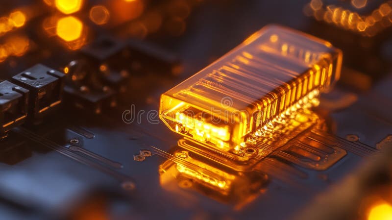
Free with trial A close-up view of a NOR flash memory module designed for embedded microcontroller applications. The illuminated circuit showcases advanced technology and design, reflecting modern electronic innovations. Microcontroller module illustrations NOR Flash Memory Module for Embedded Microcontroller Applications. A close-up view of a NOR flash memory module designed for embedded microcontroller applications. The illuminated circuit showcases advanced technology and design, reflecting modern electronic innovations
Free with trial Illustration of a printed circuit board with microcontroller, display module, and components, representing embedded systems, electronics design, IoT hardware, and PCB engineering. Microcontroller module vectors Modern electronic circuit board illustrating embedded system and microcontroller integration. Illustration of a printed circuit board with microcontroller, display module, and components, representing embedded systems, electronics design, IoT hardware, and PCB engineering.
Free with trial This image shows a small, green circuit board featuring a central microcontroller chip surrounded by various electronic components. The board has multiple connectors, including a USB port, I O pins, and a few capacitors and resistors. It appears to be designed for embedded systems or microcontroller-based projects, likely used for prototyping or as a development board. Microcontroller module illustrations Compact electronic circuit board with microcontroller and various components mounted. This image shows a small, green circuit board featuring a central microcontroller chip surrounded by various electronic components. The board has multiple connectors, including a USB port, I O pins, and a few capacitors and resistors. It appears to be designed for embedded systems or microcontroller-based projects, likely used for prototyping or as a development board
Free with trial This image shows a small electronic development board featuring a microcontroller and Bluetooth Low Energy (BLE) module. The board has multiple connectors, including a 2x17 pin header, a USB port, and a few other interface points. It appears to be designed for wireless communication applications, prototyping, or embedded systems development. The board is built on a green PCB with gold-plated. Microcontroller module illustrations Compact electronic module with bluetooth low energy and microcontroller integration. This image shows a small electronic development board featuring a microcontroller and Bluetooth Low Energy (BLE) module. The board has multiple connectors, including a 2x17 pin header, a USB port, and a few other interface points. It appears to be designed for wireless communication applications, prototyping, or embedded systems development. The board is built on a green PCB with gold-plated
Free with trial The image shows a microcontroller development board featuring multiple USB ports, a microSD card slot, and various electronic components. Next to it is a small screen display module labeled with text such as 'CPE8', 'STE F8', and 'SWDER', indicating it might be used for debugging or output purposes in embedded systems. The board appears to be a STM32-based board, commonly used for prototyping and. Microcontroller module illustrations Development board with an attached small screen display module. The image shows a microcontroller development board featuring multiple USB ports, a microSD card slot, and various electronic components. Next to it is a small screen display module labeled with text such as 'CPE8', 'STE F8', and 'SWDER', indicating it might be used for debugging or output purposes in embedded systems. The board appears to be a STM32-based board, commonly used for prototyping and
Free with trial The image shows a small Bluetooth module alongside two identical microcontroller development boards featuring multiple USB ports, capacitors, and microcontroller chips. These boards appear to be designed for embedded systems development, offering connectivity options for USB communication and wireless data transfer via Bluetooth. Microcontroller module illustrations Dual microcontroller development boards with bluetooth module and usb ports. The image shows a small Bluetooth module alongside two identical microcontroller development boards featuring multiple USB ports, capacitors, and microcontroller chips. These boards appear to be designed for embedded systems development, offering connectivity options for USB communication and wireless data transfer via Bluetooth
Free with trial A detailed illustration of an integrated electronics system featuring a battery pack, wiring harnesses, circuit boards, sensors, and a GPS module. The image highlights modular components like a microcontroller board, navigation compass, SD-like plug, and USB-style connectors, representing a compact tech setup for prototyping, development, or educational demonstrations. Suitable for technology, electronics, and engineering projects, product design, firmware testing, or instructional content focused on hardware assembly and embedded systems concepts. Microcontroller module vectors Integrated Electronics and Sensor Assembly with Battery, GPS, and Circuit Modules. A detailed illustration of an integrated electronics system featuring a battery pack, wiring harnesses, circuit boards, sensors, and a GPS module. The image highlights modular components like a microcontroller board, navigation compass, SD-like plug, and USB-style connectors, representing a compact tech setup for prototyping, development, or educational demonstrations. Suitable for technology, electronics, and engineering projects, product design, firmware testing, or instructional content focused on hardware assembly and embedded systems concepts.
Free with trial A detailed exploded-view illustration of a portable electronic system showing a microcontroller board, GPS module, Bluetooth chip, microphone, speaker array, SIM-like card, battery and a protective frame. The image highlights interconnections and integration of sensors and wireless modules within a compact device, suitable for tech tutorials, product showcases, or stock photography for consumer electronics, wearable devices, or automotive infotainment. Microcontroller module vectors Wireless Audio and GPS Module System with Microelectronics And Microphone Concept. A detailed exploded-view illustration of a portable electronic system showing a microcontroller board, GPS module, Bluetooth chip, microphone, speaker array, SIM-like card, battery and a protective frame. The image highlights interconnections and integration of sensors and wireless modules within a compact device, suitable for tech tutorials, product showcases, or stock photography for consumer electronics, wearable devices, or automotive infotainment.
Free with trial This image shows a small, green circuit board module featuring an embedded microcontroller integrated circuit. The board includes multiple gold-plated connectors for interfacing with other devices, a few resistors, capacitors, and other passive components. The layout is compact, suggesting it could be used in embedded systems or small-scale electronics projects. Microcontroller module illustrations Compact electronic module with embedded microcontroller and gold-plated connectors. This image shows a small, green circuit board module featuring an embedded microcontroller integrated circuit. The board includes multiple gold-plated connectors for interfacing with other devices, a few resistors, capacitors, and other passive components. The layout is compact, suggesting it could be used in embedded systems or small-scale electronics projects
Free with trial This image illustrates a compact wireless communication module integrated with circuit components, microcontroller, and embedded wireless capabilities, emphasizing modern electronic design and. Microcontroller module vectors Advanced wireless communication module with. This image illustrates a compact wireless communication module integrated with circuit components, microcontroller, and embedded wireless capabilities, emphasizing modern electronic design and
Free with trial Black Electronic Control Unit Module With Grid Design Isolated on White Background. Generative AI. Microcontroller module illustrations Black Electronic Control Unit Module With Grid Design Isolated on White Background
Free with trial The image shows a compact electronic circuit board module predominantly in blue color. It features a central microcontroller or integrated circuit surrounded by various passive components such as resistors, capacitors, and inductors. The board has multiple edge connectors with green and yellow pins, likely for interfacing with other devices or systems. The connectors are arranged around the. Microcontroller module illustrations Blue circuit board module with edge connectors and central microchip. The image shows a compact electronic circuit board module predominantly in blue color. It features a central microcontroller or integrated circuit surrounded by various passive components such as resistors, capacitors, and inductors. The board has multiple edge connectors with green and yellow pins, likely for interfacing with other devices or systems. The connectors are arranged around the
Free with trial This image shows a small, compact electronic module mounted on a green printed circuit board. The module includes various electronic components like capacitors, resistors, and a microcontroller or integrated circuit. It features a flat flexible cable connector on the right side and multiple through-hole connectors around the edges. The board appears to be designed for specialized applications,. Microcontroller module illustrations Compact electronic module with connectors and components on a green circuit board. This image shows a small, compact electronic module mounted on a green printed circuit board. The module includes various electronic components like capacitors, resistors, and a microcontroller or integrated circuit. It features a flat flexible cable connector on the right side and multiple through-hole connectors around the edges. The board appears to be designed for specialized applications,
Free with trial This image shows a small electronic module mounted on a green printed circuit board (PCB). The module includes an ultrasonic sensor, likely used for distance measurement, alongside a microcontroller and various supporting components such as capacitors and resistors. There are also several connection interfaces including USB and what appears to be a power input jack, along with mounting holes for. Microcontroller module illustrations Compact electronic module with ultrasonic sensor and microcontroller on green pcb board. This image shows a small electronic module mounted on a green printed circuit board (PCB). The module includes an ultrasonic sensor, likely used for distance measurement, alongside a microcontroller and various supporting components such as capacitors and resistors. There are also several connection interfaces including USB and what appears to be a power input jack, along with mounting holes for
Free with trial This image shows a small, green circuit board module with a central processor chip and multiple connectors. The board includes several mounting holes, two cylindrical connectors at the top, and a series of gold-plated pins along the bottom edge. The module appears to be designed for embedded systems, possibly for industrial or specialized computing applications. Microcontroller module illustrations Compact electronic module featuring a central processor and various interface connectors. This image shows a small, green circuit board module with a central processor chip and multiple connectors. The board includes several mounting holes, two cylindrical connectors at the top, and a series of gold-plated pins along the bottom edge. The module appears to be designed for embedded systems, possibly for industrial or specialized computing applications
Free with trial The image shows a detailed view of an embedded system processor module. The central component appears to be a CPU or microcontroller chip surrounded by various supporting electronic components. The module has multiple rows of connectors on all four sides, likely for interfacing with other hardware components. Several resistors, capacitors, and possibly memory chips are visible around the main chip. Microcontroller module illustrations Close-up view of an embedded system processor module with multiple connectors and circuitry isolated on white background. The image shows a detailed view of an embedded system processor module. The central component appears to be a CPU or microcontroller chip surrounded by various supporting electronic components. The module has multiple rows of connectors on all four sides, likely for interfacing with other hardware components. Several resistors, capacitors, and possibly memory chips are visible around the main chip
Free with trial Close-up studio shot of electronic components: a white breadboard with a black module, connected by colorful jumper wires to a blue microcontroller development board on a clean white background. Image is generated using AI. Microcontroller module illustrations Microcontroller Board and Breadboard Components. Close-up studio shot of electronic components: a white breadboard with a black module, connected by colorful jumper wires to a blue microcontroller development board on a clean white background. Image is generated using AI
Free with trial The image shows an Arduino Uno microcontroller board interfaced with a SIM900 GSM GPRS shield module. The shield is connected via several wires to the Arduino board, allowing for wireless communication capabilities such as sending SMS or connecting to the internet. This setup is commonly used for IoT (Internet of Things) projects and remote monitoring applications. Microcontroller module illustrations Arduino uno connected to a gsm gprs shield module for wireless communication. The image shows an Arduino Uno microcontroller board interfaced with a SIM900 GSM GPRS shield module. The shield is connected via several wires to the Arduino board, allowing for wireless communication capabilities such as sending SMS or connecting to the internet. This setup is commonly used for IoT (Internet of Things) projects and remote monitoring applications
Free with trial This image shows a green circuit board development platform featuring a microcontroller, multiple connectors, and various electronic components. The board includes a central microcontroller chip, several resistors and capacitors, an array of pins for interfacing, and connectors for power and data input output. It appears to be designed for prototyping and testing electronic projects, likely. Microcontroller module illustrations Development board with microcontroller and various electronic components for prototyping. This image shows a green circuit board development platform featuring a microcontroller, multiple connectors, and various electronic components. The board includes a central microcontroller chip, several resistors and capacitors, an array of pins for interfacing, and connectors for power and data input output. It appears to be designed for prototyping and testing electronic projects, likely
Free with trial The image showcases the interior of an electronic device with a prominent glowing red LED positioned centrally. The device features a metallic frame with a glass or clear acrylic panel, allowing a view of its internal components. On the right side, there are several circuit boards with visible traces and components, including connectors, a speaker, and possibly a microcontroller or similar module. Microcontroller module illustrations A glowing red led shines within a sleek electronic device. The image showcases the interior of an electronic device with a prominent glowing red LED positioned centrally. The device features a metallic frame with a glass or clear acrylic panel, allowing a view of its internal components. On the right side, there are several circuit boards with visible traces and components, including connectors, a speaker, and possibly a microcontroller or similar module
Free with trial This image shows a compact electronic circuit board featuring various components such as capacitors, resistors, integrated circuits, and connectors. The board has multiple cylindrical capacitors, a microcontroller or similar IC chip, a network transformer module, and several terminal blocks for connections. It appears to be designed for a specialized electronic application, possibly related to. Microcontroller module illustrations Electronic circuit board with multiple components and connectors. This image shows a compact electronic circuit board featuring various components such as capacitors, resistors, integrated circuits, and connectors. The board has multiple cylindrical capacitors, a microcontroller or similar IC chip, a network transformer module, and several terminal blocks for connections. It appears to be designed for a specialized electronic application, possibly related to
Free with trial This image shows an ESP32 microcontroller board featuring a dual-core Tensilica Xtensa LX6 processor operating at 240 MHz. The board includes various pins for GPIO, UART, SPI, and I2C interfaces, making it suitable for a wide range of IoT applications and embedded systems development. The module is compact and designed for low-power consumption, ideal for battery-operated devices. Microcontroller module illustrations Esp32 microcontroller board with dual core and 240 mhz processor. This image shows an ESP32 microcontroller board featuring a dual-core Tensilica Xtensa LX6 processor operating at 240 MHz. The board includes various pins for GPIO, UART, SPI, and I2C interfaces, making it suitable for a wide range of IoT applications and embedded systems development. The module is compact and designed for low-power consumption, ideal for battery-operated devices
Free with trial This image shows a small, compact electronic development board featuring a built-in camera module positioned centrally. The board includes multiple connectors such as pins for GPIO, a USB port, and a microSD card slot. It appears to be designed for embedded systems, IoT applications, or prototyping projects requiring visual data processing capabilities. Microcontroller module illustrations Compact electronic development board with camera module and multiple interface connectors. This image shows a small, compact electronic development board featuring a built-in camera module positioned centrally. The board includes multiple connectors such as pins for GPIO, a USB port, and a microSD card slot. It appears to be designed for embedded systems, IoT applications, or prototyping projects requiring visual data processing capabilities
Free with trial This image shows a small embedded circuit board featuring a central microcontroller chip surrounded by supporting electronic components. The board includes multiple connectors, such as a blue RS-485 communication module and a USB port, along with other interface points. The board appears to be designed for industrial or automation applications, providing connectivity and processing capabilities in. Microcontroller module illustrations Compact embedded circuit board with a microcontroller and expansion connectors. This image shows a small embedded circuit board featuring a central microcontroller chip surrounded by supporting electronic components. The board includes multiple connectors, such as a blue RS-485 communication module and a USB port, along with other interface points. The board appears to be designed for industrial or automation applications, providing connectivity and processing capabilities in
Free with trial This image shows a printed circuit board (PCB) featuring various electronic components including multiple integrated circuits (ICs), resistors, capacitors, and a crystal oscillator. The board appears to be designed for a specific application, potentially a microcontroller or signal processing module, with labeled ICs and a clear layout for connectivity and functionality. Microcontroller module illustrations Electronic circuit board with multiple integrated circuits and components. This image shows a printed circuit board (PCB) featuring various electronic components including multiple integrated circuits (ICs), resistors, capacitors, and a crystal oscillator. The board appears to be designed for a specific application, potentially a microcontroller or signal processing module, with labeled ICs and a clear layout for connectivity and functionality
Free with trial A rectangular metallic electronic component featuring multiple gold-plated connectors along one edge and several protruding metal pins on the opposite side. The surface has visible text markings, indicating it is likely a microcontroller or integrated circuit module used in electronic circuits. The component's design suggests it is designed for surface-mount or through-hole soldering applications. Microcontroller module illustrations Gray metal electronic component with multiple connectors and pins. A rectangular metallic electronic component featuring multiple gold-plated connectors along one edge and several protruding metal pins on the opposite side. The surface has visible text markings, indicating it is likely a microcontroller or integrated circuit module used in electronic circuits. The component's design suggests it is designed for surface-mount or through-hole soldering applications
Free with trial This image shows a printed circuit board (PCB) featuring an advanced electronic power supply module. The board includes several large cylindrical capacitors, a microcontroller or voltage regulator chip, and various other electronic components like resistors and diodes. Such modules are often used in power management systems for converting and regulating electrical power in various electronic. Microcontroller module illustrations Advanced electronic power supply module with multiple cylindrical capacitors and microchip. This image shows a printed circuit board (PCB) featuring an advanced electronic power supply module. The board includes several large cylindrical capacitors, a microcontroller or voltage regulator chip, and various other electronic components like resistors and diodes. Such modules are often used in power management systems for converting and regulating electrical power in various electronic
Free with trial This image shows a compact electronic circuit board featuring an assortment of capacitors, resistors, and a microcontroller or integrated circuit. The board appears to be designed for embedded systems, possibly serving as a voltage regulator, signal processing module, or a power management unit. It includes connectors for input output, suggesting it can interface with other electronic components. Microcontroller module illustrations Electronic circuit board with multiple capacitors and a microchip for embedded systems. This image shows a compact electronic circuit board featuring an assortment of capacitors, resistors, and a microcontroller or integrated circuit. The board appears to be designed for embedded systems, possibly serving as a voltage regulator, signal processing module, or a power management unit. It includes connectors for input output, suggesting it can interface with other electronic components
Free with trial This image shows a small electronic development board featuring a microcontroller and an integrated electret condenser microphone. The board includes a USB connector for programming and power, along with several mounting holes for secure installation. It appears designed for audio-related projects, such as voice recording, sound detection, or voice-controlled applications. Microcontroller module illustrations Compact microcontroller board with integrated microphone module for audio applications. This image shows a small electronic development board featuring a microcontroller and an integrated electret condenser microphone. The board includes a USB connector for programming and power, along with several mounting holes for secure installation. It appears designed for audio-related projects, such as voice recording, sound detection, or voice-controlled applications
Free with trial The image shows a detailed view of an electronic microcontroller board featuring a central processing unit with a teal-colored heat spreader. The board includes multiple memory module slots, capacitors, and other electronic components arranged on a black circuit board. This setup is commonly used in embedded systems and development boards for various computing applications. Microcontroller module illustrations Close-up view of a microcontroller board with central processing unit and memory modules. The image shows a detailed view of an electronic microcontroller board featuring a central processing unit with a teal-colored heat spreader. The board includes multiple memory module slots, capacitors, and other electronic components arranged on a black circuit board. This setup is commonly used in embedded systems and development boards for various computing applications
Free with trial This image shows a small, compact development board featuring a microcontroller at its center. The board is equipped with multiple pin headers around its edges, likely for connecting sensors, actuators, or other electronic modules. It appears to have a green PCB (printed circuit board) with various components, including capacitors, resistors, and possibly a voltage regulator. Such boards are. Microcontroller module illustrations Miniature circuit board with microcontroller and multiple pin headers for embedded systems. This image shows a small, compact development board featuring a microcontroller at its center. The board is equipped with multiple pin headers around its edges, likely for connecting sensors, actuators, or other electronic modules. It appears to have a green PCB (printed circuit board) with various components, including capacitors, resistors, and possibly a voltage regulator. Such boards are
Free with trial Iot circuit board module line icon vector. iot circuit board module sign. isolated contour symbol black illustration. Microcontroller module vectors Iot circuit board module line icon vector illustration. iot circuit board module line icon vector. iot circuit board module sign. isolated contour symbol black illustration
Free with trial Iot circuit board module glyph icon vector. iot circuit board module sign. isolated symbol illustration. Microcontroller module vectors Iot circuit board module glyph icon vector illustration. iot circuit board module glyph icon vector. iot circuit board module sign. isolated symbol illustration
Free with trial Electronics module kit with display and wiring components. Vector illustration for electronics tutorials, microcontroller projects, DIY kits, and educational content about display interfacing. Microcontroller module vectors LCD screen with Hello World message. Electronics module kit with display and wiring components. Vector illustration for electronics tutorials, microcontroller projects, DIY kits, and educational content about display interfacing
Free with trial The image shows a compact electronic module featuring a voltage regulator labeled 5v0f, likely a 5V DC-DC converter. The board includes multiple pins for input and output connections, a small microcontroller or integrated circuit, and three colored wires (red, black, and white) for power and signal transmission. This module is typically used for power regulation and control in various electronic. Microcontroller module illustrations Small microcontroller board with a voltage regulator and multiple pins for electronics projects. The image shows a compact electronic module featuring a voltage regulator labeled 5v0f, likely a 5V DC-DC converter. The board includes multiple pins for input and output connections, a small microcontroller or integrated circuit, and three colored wires (red, black, and white) for power and signal transmission. This module is typically used for power regulation and control in various electronic
Free with trial Iot circuit board module color icon vector. iot circuit board module sign. isolated symbol illustration. Microcontroller module vectors Iot circuit board module color icon vector illustration. iot circuit board module color icon vector. iot circuit board module sign. isolated symbol illustration
Free with trial A creative doodle-style illustration of a smart technology module. Microcontroller module vectors HandDrawn Smart Technology Module Icon. A creative doodle-style illustration of a smart technology module
Free with trial A compact embedded development board featuring a central microcontroller, two blue RAM modules, USB connectors, and various I O components. The layout highlights a professional hardware design used for prototyping, firmware development, and educational demonstrations. Suitable for illustrating electronics engineering, embedded systems, and DIY hardware projects. Perfect for showcasing product readiness, technical tutorials, and schematics references in stock photography collections or promotional materials. Microcontroller module vectors Embedded Development Board with Microcontroller and RAM Modules. A compact embedded development board featuring a central microcontroller, two blue RAM modules, USB connectors, and various I O components. The layout highlights a professional hardware design used for prototyping, firmware development, and educational demonstrations. Suitable for illustrating electronics engineering, embedded systems, and DIY hardware projects. Perfect for showcasing product readiness, technical tutorials, and schematics references in stock photography collections or promotional materials.
Free with trial This image shows a compact printed circuit board (PCB) featuring a central microcontroller or processor chip with multiple pins. The PCB includes various through-hole components and mounting holes, indicating it is designed for modular or embedded applications. The gold-colored chip is surrounded by an array of pins for connectivity, and the board itself has a green solder mask with copper pads. Microcontroller module illustrations Close-up view of a small electronic circuit board with a central microcontroller chip. This image shows a compact printed circuit board (PCB) featuring a central microcontroller or processor chip with multiple pins. The PCB includes various through-hole components and mounting holes, indicating it is designed for modular or embedded applications. The gold-colored chip is surrounded by an array of pins for connectivity, and the board itself has a green solder mask with copper pads
Free with trial System layering microcontroller illustration design protocol, abstraction hardware, software integration system layering microcontroller. Microcontroller module illustrations System layering microcontroller
Free with trial A futuristic 3D-rendered microcontroller board with a central processor chip floats above a reflective surface, surrounded by vivid rainbow neon glows, bokeh lights, and colorful gradients. Microcontroller module illustrations Vibrant 3D Rendered Microcontroller Chip on Colorful Abstract Background. A futuristic 3D-rendered microcontroller board with a central processor chip floats above a reflective surface, surrounded by vivid rainbow neon glows, bokeh lights, and colorful gradients.
Free with trial This image shows a DIP (Dual In-line Package) switch module featuring eight individual toggle switches. Each switch can be manually set to either an on or off position, allowing for multiple configuration options in electronic circuits. These switches are typically used for setting jumpers, enabling disabling features, or configuring hardware settings in devices like routers, microcontroller. Microcontroller module illustrations Dip switch module with eight toggle positions for electronic circuit configurations. This image shows a DIP (Dual In-line Package) switch module featuring eight individual toggle switches. Each switch can be manually set to either an on or off position, allowing for multiple configuration options in electronic circuits. These switches are typically used for setting jumpers, enabling disabling features, or configuring hardware settings in devices like routers, microcontroller
Free with trial This image shows a small, blue circuit board featuring a 5x7 matrix of individually programmable RGB LEDs. The board includes a microcontroller interface with pins for power, ground, data input, and clock signals. It is commonly used in electronics projects for creating dynamic displays, animations, or visual feedback systems. The LED matrix is controlled via a serial interface, making it. Microcontroller module illustrations Led matrix module with programmable rgb leds for electronic projects and microcontroller applications. This image shows a small, blue circuit board featuring a 5x7 matrix of individually programmable RGB LEDs. The board includes a microcontroller interface with pins for power, ground, data input, and clock signals. It is commonly used in electronics projects for creating dynamic displays, animations, or visual feedback systems. The LED matrix is controlled via a serial interface, making it
Free with trial This image shows a green circuit board populated with nine cylindrical capacitors arranged in a 3x3 grid and additional electronic components including microcontroller chips and resistors. The board appears to be designed for power management or filtering applications, suitable for use in various electronic devices. Microcontroller module illustrations Electronic circuit board with multiple cylindrical capacitors and microcontroller chips. This image shows a green circuit board populated with nine cylindrical capacitors arranged in a 3x3 grid and additional electronic components including microcontroller chips and resistors. The board appears to be designed for power management or filtering applications, suitable for use in various electronic devices
Free with trial Vector illustration of an Arduino Mega Microcontroller color drawings. Microcontroller module vectors Arduino Mega Microcontroller
Free with trial This image shows a small, blue circuit board module designed for embedded systems. It features a buzzer or speaker component for audio output, a micro USB port for power and data connectivity, and various electronic components including resistors, capacitors, and a microcontroller. The module appears to be designed for integration into larger projects requiring compact audio signaling or alerts. Microcontroller module illustrations Compact electronic module with buzzer and micro usb port for embedded systems applications. This image shows a small, blue circuit board module designed for embedded systems. It features a buzzer or speaker component for audio output, a micro USB port for power and data connectivity, and various electronic components including resistors, capacitors, and a microcontroller. The module appears to be designed for integration into larger projects requiring compact audio signaling or alerts
Free with trial The image shows a small, green circuit board featuring a central microcontroller chip surrounded by various electronic components. Visible elements include capacitors, resistors, and connectors, suggesting it is designed for embedded systems or specialized computing tasks. The board has multiple mounting holes and a connector interface on the right side, likely for power or data transmission. It. Microcontroller module illustrations Compact electronic circuit board with microcontroller and capacitors for embedded systems applications. The image shows a small, green circuit board featuring a central microcontroller chip surrounded by various electronic components. Visible elements include capacitors, resistors, and connectors, suggesting it is designed for embedded systems or specialized computing tasks. The board has multiple mounting holes and a connector interface on the right side, likely for power or data transmission. It
Free with trial This image shows a small embedded circuit board featuring a central microcontroller chip labeled 'ic'. The board includes multiple connectors, capacitors, and mounting holes, likely designed for integration into larger electronic systems or devices. It appears to have power input output terminals and possibly communication interfaces for data transfer or control purposes. Such boards are commonly. Microcontroller module illustrations Embedded circuit board with microcontroller and multiple connectors for electronic applications. This image shows a small embedded circuit board featuring a central microcontroller chip labeled 'ic'. The board includes multiple connectors, capacitors, and mounting holes, likely designed for integration into larger electronic systems or devices. It appears to have power input output terminals and possibly communication interfaces for data transfer or control purposes. Such boards are commonly
Free with trial Close-up image of a red printed circuit board featuring a central microcontroller chip surrounded by various electronic components, connectors, and soldered traces. Perfect for tech, electronics, and engineering projects or educational materials. Microcontroller module illustrations Red electronic circuit board with microcontroller and connectors. Close-up image of a red printed circuit board featuring a central microcontroller chip surrounded by various electronic components, connectors, and soldered traces. Perfect for tech, electronics, and engineering projects or educational materials
Free with trial A top-down view of an electronic alphanumeric lcd display module with a bright blue backlight, mounted on a green printed circuit board with visible soldered components. Microcontroller module vectors Blue character lcd module with circuit board. A top-down view of an electronic alphanumeric lcd display module with a bright blue backlight, mounted on a green printed circuit board with visible soldered components
Free with trial This image shows a detailed view of a gray microcontroller chip featuring the brand name 'Microchip' engraved on its surface. The chip has two rows of orange-colored pins on each side, designed for insertion into a circuit board. Such components are commonly used in various electronic devices for controlling operations and processing data. Microcontroller module illustrations Close-up view of a gray microcontroller chip with orange pins for electronic applications. This image shows a detailed view of a gray microcontroller chip featuring the brand name 'Microchip' engraved on its surface. The chip has two rows of orange-colored pins on each side, designed for insertion into a circuit board. Such components are commonly used in various electronic devices for controlling operations and processing data
Free with trial The image shows a Raspberry Pi Compute Module 4, a compact development board designed for embedded applications. It is mounted on a carrier board, featuring multiple ports including USB, Ethernet, and HDMI. The module itself is a small, square-shaped board with various connectors and a central processor. The carrier board provides additional functionality and connectivity options, making it. Microcontroller module vectors Raspberry pi compute module 4 with attached circuit board. The image shows a Raspberry Pi Compute Module 4, a compact development board designed for embedded applications. It is mounted on a carrier board, featuring multiple ports including USB, Ethernet, and HDMI. The module itself is a small, square-shaped board with various connectors and a central processor. The carrier board provides additional functionality and connectivity options, making it
Free with trial Architecture layering microcontroller illustration firmware embedded, system design, protocol abstraction architecture layering microcontroller. Microcontroller module illustrations Architecture layering microcontroller
Free with trial Explore a vibrant depiction of a microcontroller on an advanced circuit board, embodying the essence of smart home automation technology and innovation. Microcontroller module illustrations Smart Home Automation Microcontroller on Electronic Circuit Board. Explore a vibrant depiction of a microcontroller on an advanced circuit board, embodying the essence of smart home automation technology and innovation
Free with trial Detailed 3D Illustration of a Microcontroller Unit MCU Development Board with Colorful Buttons and Pins for STEM and Programming , aesthetic background. Microcontroller module illustrations Detailed 3D Illustration of a Microcontroller Unit MCU Development Board with Colorful Buttons and Pins for STEM an
Free with trial A clean, modern icon of a blue microcontroller chip with circuit elements, perfect for tech and electronics stock graphics. Microcontroller module illustrations Blue microcontroller circuit board chip icon. A clean, modern icon of a blue microcontroller chip with circuit elements, perfect for tech and electronics stock graphics
Free with trial The image showcases a professional arrangement of electronic components against a stark black background, emphasizing a technical and precise atmosphere. Central to the composition is a blue OLED display module connected via wires to a vibrant blue circuit board featuring multiple header pins and a microcontroller interface. Red and orange wires add visual contrast, while a small label marked 'web. Microcontroller module illustrations Electronic Hardware Components for IoT Development Setup. The image showcases a professional arrangement of electronic components against a stark black background, emphasizing a technical and precise atmosphere. Central to the composition is a blue OLED display module connected via wires to a vibrant blue circuit board featuring multiple header pins and a microcontroller interface. Red and orange wires add visual contrast, while a small label marked 'web
Free with trial This image showcases an LED matrix display housed in a metallic frame, featuring a grid of individually addressable LEDs. The display appears to be segmented into three color zones: blue, green, and a combination of both. Wires connected to the sides suggest it is ready for integration with a microcontroller or power supply for programming and operation. The setup is likely used for visual. Microcontroller module illustrations Led matrix display module with wired connections. This image showcases an LED matrix display housed in a metallic frame, featuring a grid of individually addressable LEDs. The display appears to be segmented into three color zones: blue, green, and a combination of both. Wires connected to the sides suggest it is ready for integration with a microcontroller or power supply for programming and operation. The setup is likely used for visual
Free with trial Electronic components with cables, connectors and microcontroller boards arranged on a clean background, modern hardware development, engineering and digital technology concept. High. Microcontroller module illustrations Electronic components with cables, connectors and microcontroller boards arranged on a clean background, modern hardware. Development, engineering and digital. Electronic components with cables, connectors and microcontroller boards arranged on a clean background, modern hardware development, engineering and digital technology concept. High
Free with trial The image shows a green printed circuit board (PCB) with a black camera module affixed at the top. The camera module includes a lens and is connected to the PCB via wires and connectors. There are electronic components and traces visible on the PCB, and the overall setup suggests a hardware or electronics project, likely for photography or computer vision applications. Microcontroller module illustrations A green circuit board with a black camera module attached. The image shows a green printed circuit board (PCB) with a black camera module affixed at the top. The camera module includes a lens and is connected to the PCB via wires and connectors. There are electronic components and traces visible on the PCB, and the overall setup suggests a hardware or electronics project, likely for photography or computer vision applications
Free with trial Close-up of a detailed microcontroller board featuring multiple pins for electronics projects and programming. Microcontroller module illustrations Blue microcontroller development board with pins. Close-up of a detailed microcontroller board featuring multiple pins for electronics projects and programming
Free with trial Clean and stylish vector icon of a microcontroller chip with pins, perfect for tech and electronics design projects. Microcontroller module vectors Modern black chip microcontroller integrated circuit icon. Clean and stylish vector icon of a microcontroller chip with pins, perfect for tech and electronics design projects
Free with trial An isolated single channel relay module board featuring a blue relay and screw terminals for connecting high voltage circuits safely in automation systems. Microcontroller module illustrations Single Channel Relay Module for DIY Electronics Projects. An isolated single channel relay module board featuring a blue relay and screw terminals for connecting high voltage circuits safely in automation systems
Free with trial Close-up of a detailed electronic development board featuring a central microcontroller and capacitors. Microcontroller module illustrations Blue circuit board with microcontroller chip and capacitors. Close-up of a detailed electronic development board featuring a central microcontroller and capacitors
Free with trial Close-up of a detailed electronic development board featuring a central microcontroller and capacitors. Microcontroller module illustrations Blue circuit board with microcontroller chip and capacitors. Close-up of a detailed electronic development board featuring a central microcontroller and capacitors
Free with trial A close-up view of a NOR flash memory module embedded on a circuit board showcases intricate electronic connections, emphasizing modern technology and innovative design. Microcontroller module illustrations Detailed View of NOR Flash Memory Module on Circuit Board. A close-up view of a NOR flash memory module embedded on a circuit board showcases intricate electronic connections, emphasizing modern technology and innovative design
Free with trial A detailed illustration of a timing master microcontroller circuit featuring a crystal oscillator, MHz clock source, resistors, and a digital display. The diagram showcases interconnections between the oscillator, timing IC, voltage regulators, and display module, highlighting practical uses in embedded systems, timing regulation, and synchronized electronics. Suitable for tech tutorials, product photography, and educational content about clock circuits and digital timing in devices. Microcontroller module vectors Electronic Timing Master Circuit with Crystal Oscillator and Display. A detailed illustration of a timing master microcontroller circuit featuring a crystal oscillator, MHz clock source, resistors, and a digital display. The diagram showcases interconnections between the oscillator, timing IC, voltage regulators, and display module, highlighting practical uses in embedded systems, timing regulation, and synchronized electronics. Suitable for tech tutorials, product photography, and educational content about clock circuits and digital timing in devices.
Free with trial This image shows a green printed circuit board (PCB) featuring a parallel port connector in the center, surrounded by various electronic components. The board includes microcontroller chips, capacitors, resistors, and other passive components. The PCB appears to be designed for interfacing or communication purposes, likely used in embedded systems or data acquisition applications. The board has a. Microcontroller module illustrations Green circuit board with parallel port connector and microcontroller chips. This image shows a green printed circuit board (PCB) featuring a parallel port connector in the center, surrounded by various electronic components. The board includes microcontroller chips, capacitors, resistors, and other passive components. The PCB appears to be designed for interfacing or communication purposes, likely used in embedded systems or data acquisition applications. The board has a
Free with trial High-quality close-up of a Raspberry Pi microcontroller circuit board, ideal for tech tutorials, DIY projects, electronics education, and IT hardware marketing. Microcontroller module illustrations Blue raspberry pi microcontroller circuit board isolated on white background. High-quality close-up of a Raspberry Pi microcontroller circuit board, ideal for tech tutorials, DIY projects, electronics education, and IT hardware marketing
Free with trial Close Up of Black Electronic Control Module for Automotive Systems Isolated. Generative AI. Microcontroller module illustrations Close Up of Black Electronic Control Module for Automotive Systems Isolated
Free with trial The image shows a compact electronic circuit board featuring a microcontroller or module labeled 'MCSG S32 M1' and four BNC connectors. This board is likely used for signal processing, data acquisition, or communication purposes, given its connectors and compact design. The module appears to be connected to a cable, suggesting it is part of a larger system requiring precise signal handling. Microcontroller module illustrations Miniature circuit board with bnc connectors for signal processing applications. The image shows a compact electronic circuit board featuring a microcontroller or module labeled 'MCSG S32 M1' and four BNC connectors. This board is likely used for signal processing, data acquisition, or communication purposes, given its connectors and compact design. The module appears to be connected to a cable, suggesting it is part of a larger system requiring precise signal handling
Free with trial This image shows a green electronic circuit board featuring a central microcontroller chip that is emphasized with an orange arrow. The board includes multiple connectors, capacitors, resistors, and a blue edge connector, likely used for expansion or interfacing with other devices. It appears to be a development or control board for embedded systems applications. Microcontroller module illustrations Electronic circuit board with a highlighted microcontroller chip and connectors. This image shows a green electronic circuit board featuring a central microcontroller chip that is emphasized with an orange arrow. The board includes multiple connectors, capacitors, resistors, and a blue edge connector, likely used for expansion or interfacing with other devices. It appears to be a development or control board for embedded systems applications
Free with trial The image shows a small, blue printed circuit board featuring a central microcontroller chip labeled with an 'A'. The board has intricate circuit traces and multiple through-hole components. A USB type-A connector is present on the left side, indicating connectivity options for programming or power supply. The overall design suggests it could be used in embedded systems or DIY electronics projects. Microcontroller module illustrations Close-up view of a blue circuit board with a microcontroller chip and usb connector. The image shows a small, blue printed circuit board featuring a central microcontroller chip labeled with an 'A'. The board has intricate circuit traces and multiple through-hole components. A USB type-A connector is present on the left side, indicating connectivity options for programming or power supply. The overall design suggests it could be used in embedded systems or DIY electronics projects